[Elixir Nerves] Smoothly dimming LEDs using a servo driver
![[Elixir Nerves] Smoothly dimming LEDs using a servo driver](/_next/image?url=https%3A%2F%2Fcdn.hashnode.com%2Fres%2Fhashnode%2Fimage%2Fupload%2Fv1612786153663%2Fc-Aet34L-.gif&w=3840&q=75)
It is so pleasant to do the IoT programming in Elixir thanks to the Nerves IoT platform. Elixir allows us to write beautiful, fluent and readable code for problems that would look scary in other languages. This is another random study note about my learning electronics through Elixir programming.
Anyway, today I feel like controlling the brightness of LEDs from my Raspberry Pi Zero W that is powered by the Nerves IoT platform. Before getting started, we need to understand what the Pulse Width Modulation (PWM) is and how we can use PWM from a Raspberry Pi if not already.
Pulse Width Modulation (PWM)
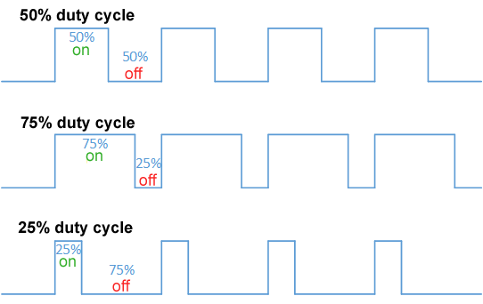
Long story short, it is about controlling the ratio of on-time to off-time of the waveform. In other words, we express analog data using digital signals. I personally like this image below from Wikipedia because it explains very concisely what PWM essentially is.
In the context of controlling an LED through GPIO, we can do two things using PWM, which was intriguing to me when I first learned it.
1. blink an LED with various on/off timings
When the frequency (Hz) is low for example 1-2Hz, we can actually see the LED switching on and off on a regular basis. So by changing the duty cycle, we can change the timing of the blinking. It is fun.
2. change the brightness of an LED
As the frequency goes higher for example up to 100Hz, we no longer can observe the blinking beyond a certain point. With such a frequency, the duty cycle acts like the brightness. In other words, we can consider the area of the graph of the waves as the brightness. They say this technique of converting digital signal into analog is quite common and is applied to many different things such as controlling a servo motor.
How to use PWM from Raspberry Pi
Roughly speaking there are two ways to control PWM from Raspberry Pi.
1. Raspberry Pi's onboard PWM module
According to Raspberry Pi's GPIO usage documentation, here are the pins that PWM is available on:
- GPIO12
- GPIO13
- GPIO18
- GPIO19
In Elixir, the pigpiox library provides functions that allow us to build and send waveforms with pigpio daemon.
gpio = 12
frequency = 100

# I don't know what unit it is but `1_000_000` was the maximum value.
Pigpiox.Pwm.hardware_pwm(gpio, frequency, 1_000_000)
2. External PWM module
Using an external servo driver board like Adafruit 16-Channel PWM/Servo Driver, we have more flexibility with more channels. The downside was there was no Elixir library for using that servo driver; however as I studied Adafruit's official Python code, it was not easy but not rocket science either. So I decided to write my own library in Elixir. It would be great if it helps other alchemists. The key thing is that board uses PCA9685 PWM controller, so the chip's data sheet is the single source of truth.
Using the mnishiguchi/servo_kit library, here is how to change the brightness of an LED.
# Initialize a driver.
driver = ServoKit.PCA9685.new(%{i2c_bus: "i2c-1", frequency: 100})

# Set the duty cycle to 66.6% for Channel 15.
ServoKit.PCA9685.set_pwm_duty_cycle(driver, 15, 66.6)
Demo
Hardware
Here are the items I prepared:
- Raspberry Pi Zero W
- I use and love [this Pi case] (https://www.adafruit.com/product/2883) for a HAT
- Micro SD card
- I burn Nerves firmware on a micro SD card.
- Adafruit 16-Channel PWM / Servo Bonnet for Raspberry Pi
- 5V 2A (2000mA) switching power supply
- jumber wires
- 220ohm resistors
- LEDs
Software
- Nerves - IoT platform built with Elixir
- mnishiguchi/servo_kit - Use PCA9685 PWM/Servo Controller in Elixir
Wiring
I use channel 0, 4 and 8. The servo connectors have three pins for each channel:
- Control Signal
- Power Supply
- Ground
But for LEDs, all we need is control signals and common ground.


Programming
Here is the code I wrote for this demo. It was inspired by Adafruit's RGB Backlit LCDs tutorial.
driver = ServoKit.PCA9685.new(%{i2c_bus: "i2c-1", frequency: 100})

ch_red = 0
ch_green = 4
ch_blue = 8

loop_fn = fn loop_fn ->
  (0..99) |> Enum.each(fn x ->
    driver
    |> ServoKit.PCA9685.set_pwm_duty_cycle(ch_red, x)
    |> ServoKit.PCA9685.set_pwm_duty_cycle(ch_green, 0)
    |> ServoKit.PCA9685.set_pwm_duty_cycle(ch_blue, 99 - x)
    Process.sleep(50)
  end)

  (0..99) |> Enum.each(fn x ->
    driver
    |> ServoKit.PCA9685.set_pwm_duty_cycle(ch_red, 99 - x)
    |> ServoKit.PCA9685.set_pwm_duty_cycle(ch_green, x)
    |> ServoKit.PCA9685.set_pwm_duty_cycle(ch_blue, 0)
    Process.sleep(50)
  end)

  (0..99) |> Enum.each(fn x ->
    driver
    |> ServoKit.PCA9685.set_pwm_duty_cycle(ch_red, 0)
    |> ServoKit.PCA9685.set_pwm_duty_cycle(ch_green, 99 - x)
    |> ServoKit.PCA9685.set_pwm_duty_cycle(ch_blue, x)
    Process.sleep(50)
  end)

  loop_fn.(loop_fn)
end

loop_fn.(loop_fn)
Conclusion
To me as an electronics noob, PWM looked a bit scary at first, but once getting used to it, its basic use is relatively easy. Specialists seem to precisely calculate and monitor the waveform, but I guess casual hobbyists do not need to worry about it.
Armed with PWM, we can go further, using a potentiometer, controlling a servo, changing RGB-backlit LCD display's background colors, etc.
